Make Your Own Internet Connected Thermostat
During a brief stint of funemployment I decided to make an internet controllable thermostat for our apartment. While I had our normal thermostat on a schedule, it would be nice to turn it off before a trip and be able to turn it back on from my phone during the car ride home. You can buy a smart thermostat like a Nest, but they’re either very expensive or equally hard to use. Anyways, it’s more fun to build things yourself.
With no expertise in HVAC, I had no idea how thermostats worked. They obviously measure the temperature and communicate with the heater, but beyond that I had no idea. This (lack of) knowledge in hand, my first step was to pull the thermostat off the wall and start playing around. I found two wires leading to terminals that ran into the wall. On a hunch, after verifying that the terminals didn’t carry high voltage, I connected them with a jumper cable. Success! The heater turned on. Further investigation revealed that these wires controlled a gas valve that could be opened and shut in our heater. When current was allowed to travel across the terminals the valve opened, turning on the heat.
At this point, I was pretty excited. If turning the heat on was as simple as making a connection between 2 wires, making our own thermostat should be trivial. Indeed, the design and implementation was quite straightforward. Without further ado, here’s my recipe for your own internet connected thermostat.
Ingredients: #
- Electric Imp (the brains) ~$25
- Electric Imp breakout board ~$12
- TMP102 Ambient Tempurature Sensor + Breakout~$6
- Jumper wires, resistors, LEDs. We found this kit to be pretty good~$20
- Soldering Iron
- Solder
- Optoisolator Relay ~$5
- Breakaway Headers ~$1
- Jumper pins
If you already have the “general electronics” sorts of components the total cost is a very reasonable $50. Many of these parts can probably also be found slightly more cheaply on digikey if you’re into that sort of thing.
We’ll be using the Electric Imp as the brains of the project. The Electric Imp is a SD-card-sized microcontroller that enables you to easily connect your projects to the internet. There are many microcontrollers to choose from, and the Imp certainly isn’t the best in general. You can only code it in the somewhat kludgey online IDE and you rely on their platform to deliver messages to your Imp. It supports a limited set of data protocols for talking to sensors. All these things aside, it fits our needs well:
- Integrated Wifi: Getting WIFI with an Arduino is still surprisingly difficult and expensive – people even use the Imp as an easy way to get Arduinos online.
- Built-in web presence: Every Electric Imp comes with an HTTPS URL that uniquely communicates securely (assumed, not verified) with your Imp. You can write both code that runs on the server and code that runs on the Imp to handle web requests and send the Imp messages.
- Convenient programming language: The Electric Imp uses Squirrel, which, although also kludgey and poorly documented, makes the kind of event driven programming you’ll want to do very straightforward.
Stop! Read this and solder the headers to the Electric Imp. Do the basic Imp tutorial to get your Imp set up and learn how to use the online IDE.
Let’s talk briefly about the mechanics of what we need to accomplish. After choosing our desired temperature, our thermostat will spend most of it’s time in a 3 step loop:
- Read ambient temperature.
Decide whether to turn on the heat:
if temperature > set, Heat OFF
if temperature < set, Heat ON
Wait 1 minute, then Step 1.
If we were to rewrite this in code, it might look something like this:
setPoint <- 68;
function updateTemp() {

  // Read the ambient temperature
  temp <- readTemp();

  // If it's below what it should be, turn on the heat.
  if (temp < setPoint) {
    heatOn();
  } else {

    // If it's not below, that means it's above. Turn the heat on!
    heatOff();
  }
}

function mainLoop() {
   updateTemp();
   // in 60 seconds, call mainLoop again
   imp.wakeup(60, mainLoop);
}

// start the mainLoop:
mainLoop();
We’ll need to build circuitry to read the ambient temperature of the room as well as well as circuitry to turn the heat on and off. First, we’ll discuss how we’ll control the heat.
How will we implement heatOn() and heatOff()?
Recall from the beginning of the article that all that’s needed to turn the heat on and off is completing and breaking an electrical circuit. We must make a switch that we can open and close with the other electronics we already have. Specifically, the Electric Imp can set any one of its 7 pins to any voltage between 0 and 3.3. We’ll use that voltage to flip our switch. Traditionally, there are two ways to go about this.
Transistors: A transistor is an electrical switch that works be pulling electrons in a doped silicon structure to allow current to flow. They can be tricky to use for several reasons:
- Current can only flow in one direction
- Sensitive to overvoltage and environmental issues
- Complicated to wire up
Relays: A relay is a mechanical switch where the switch element is actually physically actuated by our switching voltage. They are much simpler to use, but have the disadvantage of much slower switching since a mechanical part must move. They can also be much more expensive than transistors. In a thermostat, we have no need for submicrosecond switching, and the added complexities of transistors will only cause issues. A relay is the better choice.
For this project, we’ll be using a specific kind of relay called an optoisolator. It works by shining a light on a photoresistor. When light is shined on the photoresistor, it changes from “closed” to “open” and allows current to flow. We’ll connect the control ports of the relay to the Electric Imp and the output ports of the relay to the wires in your thermostat. When we raise the voltage in the Imp, it will close the relay allowing current to flow across the thermostat wires. When this happens, the heat will turn on! We’ll want to start by testing this circuit out with an LED. The following diagram shows how you could wire this up (but don’t do that just yet):

Lets revisit our code from before. We still need to provide definitions for heatOn, heatOff, and readTemp. Now, we should be able to figure out how to implement heatOn() and heatOff()
// heatControlWire lets us control pin1 of the Electric Imp.
heatControlWire <- hardware.pin1;

// Configure it so that when we write 1 to heatControlWire,
  // the pin voltage will be driven to 3.3v.
  // When we write 0, it will be driven to 0 volts
heatControlWire.configure(DIGITAL_OUT);
function heatOn() {
    // debug message so you know what the Imp is doing
    server.log("heat is on");
    heatControlWire.write(1);
}

function heatOff() {
    server.log("heat is off");
    heatControlWire.write(0);
}
Lets test this out! The only thing we’re missing is a function to return the temperature. For the moment, we’ll “stub” this method to just return a number.
function readTemp() {
    return 60;
}
The code at this point should look like: this
It’s time to test it out! Start by wiring up this circuit:
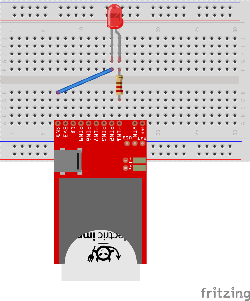
If you deploy the code to your Imp and setpoint is greater than 60, the LED should turn on. If you change the the value returned in readTemp to be 70, the LED (“heat”) should turn off and you should see a log message printed.
Now that we have the basics working, wire up the circuit with a relay:
The exact same behavior should happen. To plug into an actual thermostat, you’ll want to wire the terminals to the ~ outputs on the relay.
Wiring up the thermometer #
We’re getting close to a working thermostat! We’re just missing one piece: reading the temperature. For temperature readings, we’ll be using the TMP102 sensor. It was chosen for it’s high accuracy, low price, and protocol compatible with the Electric Imp. The TMP102 uses a protocol called i2c. Here’s what you need to know about i2c:
i2c (pronounced “i squared c”) uses two communication wires, SDA and SCL. The Imp has 2 groups of 2 ports that support i2c: ports 1 & 2 and ports 8 & 9. When you initialize i2c in the Imp, you specify the which ports you are using. SDA always connects to the lower of the two ports.
Our temperature sensor must also be connected to power and ground. Here’s a diagram for the completed circuit (your sensor may look slightly different):

Newer versions of the TMP102 have all the ports on one side. alt doesn’t need to be connected to anything, but ADD0 must be connected to ground.
Note that we’ve moved the heater control from pin1 to pin5 to make way for the TMP102. You only need to change:
// Remove:
// heatControlWire <- hardware.pin1;
// Replace it with:
heatControlWire <- hardware.pin5;
To read from the temperature sensor, just copy and paste this code
To use the sensor, we’ll first need to declare it: (We’re using i2c ports 1 & 2)
sensor <- TemperatureSensor(hardware.i2c12);
Reading the temperature is as easy as changing `readTemp() to:
function readTemp() {
    server.log("reading temperature: ");
    temp <- sensor.getTemperature('F');
    server.log(temp);
    return temp;
}
Your code should look like this.
That’s it! At this point you should have the beginnings of a working thermostat! Getting the TMP102 working may be a little tricky. Here are some things to double check:
- SDA and SCL are connected in the right order. SDA should be connected to pin 2 and SCL should be connected to pin 1. SDA is always connected to the higher of the 2 pins when using the Electric Imp.
- ADD0 must be grounded.
- Verify electric connections with a multimeter.
- If you are using 1 & 2 for communication, try 8 & 9 or vice versa. On some Imps these pins have been known to be bad, and it’s possible one of them has a a bad solder joint.
Wrap up:
So far, we’ve set up our Imp with a temperature sensor to read the temperature and a really to control it. We’ve written some simple code to check the temperature and update the heat accordingly.
In the next segment we’ll cover the currently missing piece: Easy internet control.
Thanks to Leah for helping to edit this post.